
Profiles in Current: Fast Insights into Battery Charge Consumption
Article Reprints
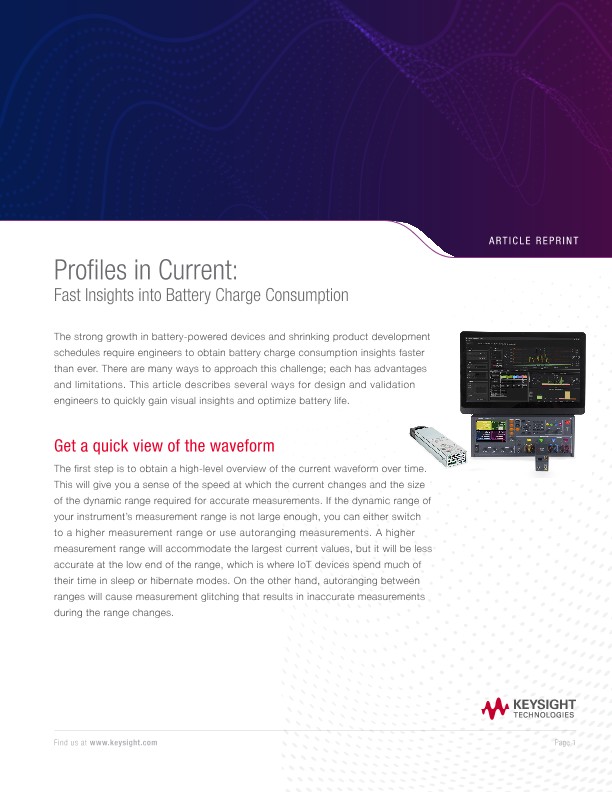
The strong growth in battery-powered devices and shrinking product development schedules require engineers to obtain battery charge consumption insights faster than ever. There are many ways to approach this challenge; each has advantages and limitations. This article describes several ways for design and validation engineers to quickly gain visual insights and optimize battery life.
Get a quick view of the waveform
The first step is to obtain a high-level overview of the current waveform over time. This will give you a sense of the speed at which the current changes and the size of the dynamic range required for accurate measurements. If the dynamic range of your instrument’s measurement range is not large enough, you can either switch to a higher measurement range or use autoranging measurements. A higher measurement range will accommodate the largest current values, but it will be less accurate at the low end of the range, which is where IoT devices spend much of their time in sleep or hibernate modes. On the other hand, autoranging between ranges will cause measurement glitching that results in inaccurate measurements during the range changes.
Zoom in to view details
Once you have an overall sense of the waveform, the next step is to zoom in on the current waveform and examine the subtle variations in current consumption. The waveform may give the appearance that the device is simply switching between low-power sleep modes and full-on operation, but the zoomed waveform reveals a more complex picture that prompts interesting questions about device behavior. For example, in Figure 2, what event is causing those three large spikes? Why do they appear to be evenly spaced, how long do they last, and how much charge do they consume?
Time-slice the waveform
To help answer questions about the device’s charge consumption, device design and validation, engineers use a technique called event-based power analysis to gain insights into the RF and sub-circuit events associated with various current levels. Engineers can time-slice the current waveform based on these events to quickly understand how various events are associated with charge consumption during a user-defined period of operation.
For example, in Figure 3, the yellow trace shows current over time, and the green trace shows RF power at the same time scale. These pulses of RF power are clearly synchronized with the highest pulses in the current waveform.
Get the numbers fast from a table
A visual image is useful, and engineers also like numeric data. Looking at a tabular view of statistics associated with a time-sliced waveform gives engineers the information they need to quantify their device’s performance under various conditions.
For example, the table in Figure 4 clearly shows that more than a quarter of this device’s charge consumption occurred in periods of relatively high RF power. During the same period, the device was in Standby (low current) mode nearly half the time, but less than three percent of the current consumption occurred in Standby mode. The table also shows what did not happen during the selected time frame. For example, we can conclude that the LED supply voltage, which powers a nominal 3.5-V LED, never went up to a value between 2 and 5 volts because both the Time Consumed and Charge Consumed show zero.
Get relative consumption data at a glance
Sometimes, of course, the visual impact of a bar chart is helpful. For example, the chart in Figure 5 provides the same data that is available in the Charge Consumed row of the table in Figure 4, but many people appreciate being able to get the key point at a glance.
Understand time and charge consumption vs. current
Where the bar chart is a clear and intuitively obvious way to view data, another tool, known as the complementary cumulative distribution function (CCDF) takes a bit more explanation. However, it also provides rich data that cannot be found in other graphical images. The CCDF has one or more lines that always start at 100% and go to 0% in the vertical axis as the current level increases in the X axis. For example, the CCDF in Figure 6 has a blue line for charge consumption and a yellow line that shows how time is spent. The horizontal axis uses a logarithmic scale to denote current levels from 1 μA to 1 A.
In Figure 6, the user’s mouse pointer is hovering at about 41 μA on the X axis, and the blue and yellow tool tips show Y values of approximately 99 and 60 percent. This means that the device spends about 60 percent of its time at current levels above 41 μA, but more than 99 percent of its charge is consumed at current levels above 41 μA. Of course, the graph can also be read in the opposite, left-facing way: the device spends about 40 percent of its time but less than one percent of its charge at currents below 41 μA.
The key insights in a CCDF are generally found where there are steep vertical drops or long plateaus. For example, the device spends about 40 percent of its time at currents of approximately 40 μA, but relatively little time between 40 μA and 1 mA. The long plateau on the blue (charge) line indicates that the device consumes very little charge at currents below 1 mA, and it consumes significant charge at currents very near to 10 mA. Of course, some CCDF software allows you to zoom in on charts to obtain more precise information.
The CCDF chart also allows the design engineer to document changes in device operation over time. For example, it might be useful to compare CCDF charts when the device operating with different versions of firmware or different processors.