
Antenna Measurement Theory
Article Reprints
Basic Concepts
ELECTROMAGNETIC WAVES
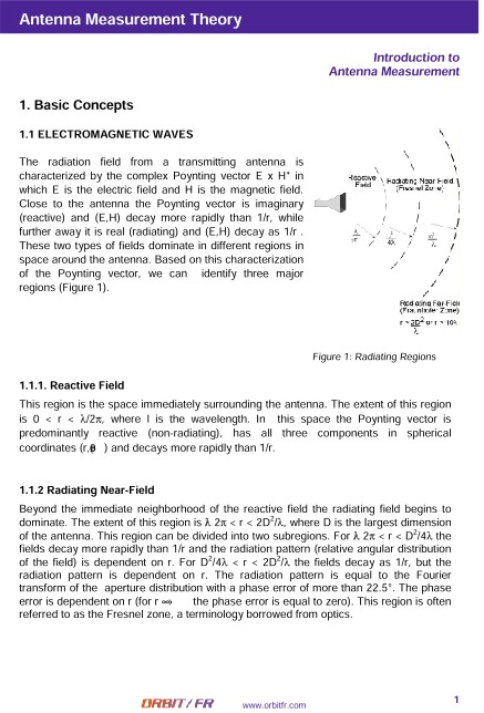
The radiation field from a transmitting antenna is characterized by the complex Poynting vector E x H* in which E is the electric field and H is the magnetic field. Close to the antenna the Poynting vector is imaginary (reactive) and (E,H) decay more rapidly than 1/r, while further away it is real (radiating) and (E,H) decay as 1/r . These two types of fields dominate in different regions in space around the antenna. Based on this characterization of the Poynting vector, we can identify three major regions
Reactive Field
This region is the space immediately surrounding the antenna. The extent of this region is 0 < r < λ/2π, where l is the wavelength. In this space the Poynting vector is predominantly reactive (non-radiating), has all three components in spherical coordinates (r,θ,φ) and decays more rapidly than 1/r.
Radiating Near-Field
Beyond the immediate neighborhood of the reactive field the radiating field begins to dominate. The extent of this region is λ/2π < r < 2D2/λ, where D is the largest dimension of the antenna. This region can be divided into two subregions. For λ/2π < r < D2/4λ the fields decay more rapidly than 1/r and the radiation pattern (relative angular distribution of the field) is dependent on r. For D2/4λ < r < 2D2/λ the fields decay as 1/r, but the radiation pattern is dependent on r. The radiation pattern is equal to the Fourier transform of the aperture distribution with a phase error of more than 22.5°. The phase error is dependent on r (for r →∞ the phase error is equal to zero). This region is often referred to as the Fresnel zone, a terminology borrowed from optics.
Radiating Far-Field
Beyond the radiating Near-Field region r > 2D2/λ or r > 10l (criterion for small antennas) the Poynting vector is real (only radiating fields) and has only two components in spherical coordinates (θ,φ). The fields decay as 1/r and the radiation pattern is independent of r. The radiation pattern in this region is approximated by the Fourier transform of the aperture distribution with a phase error of less than 22.5°. This region is often referred as the Fraunhofer zone, a terminology borrowed from optics.
ANTENNA PARAMETERS
Antenna
The antenna is a device which transforms guided electromagnetic signals into electromagnetic waves propagating in free space. It can be used for reception and transmission.
Polarization
Polarization is the property of the electric field vector that defines variation in direction and magnitude with time. If we observe the field in a plane perpendicular to the direction of propagation at a fixed location in space, the end point of the arrow representing the instantaneous electric field magnitude traces a curve. In the general case, this curve is an ellipse (Figure 2). The ellipse can be characterized by the axial ratio (AR), the ratio of the two major axes and its tilt angle t. Polarization may be classified as linear, circular or elliptical according to the shape of the curve. Linear and circular polarization are special cases of elliptical polarization, when the ellipse becomes a straight line or circle, respectively. Clockwise rotation of the electric field vector is designated as righthand polarization (RH) and counterclockwise rotation is left-hand polarization (LH), for an observer looking in the direction of propagation.