What are you looking for?
Charge measurement
1. Electric charge measurement
The measurement of the quantity of electric charge is a basic measurement though it is not widely used as the voltage and current measurement etc. It is often used in case measuring the other parameters by measuring the quantity of electric charge is included.
1.1 Measuring the electric charge
The meters named as coulomb meters and charge amplifiers are being sold as the electric charge measuring devices. The meters with the function to measure both the minute electric current and the electric charge is often called an electrometer.
The example of items measured for the quantity of electric charge are ESD, powder etc.
ESD is the failure cause of electronic parts, and hence it is measured for the evaluation of the quantity of electric charge of the electrical discharge.
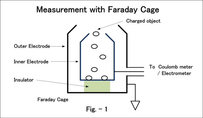
The Faraday cage and coulomb meter are often used when measuring the electrostatic charge of the powder. (Refer to Fig.-1). It is common to add the electrostatic charged powder in the Faraday cage, and measure the electric charge coming at that time with the coulomb meter or electrometer. It is basic to measure the aggregate of these electric charges, and the time fluctuation is not assumed as the problem.
We can also obtain the voltage (variation value) by measuring the quantity of electric charge. If the quantity of electric charge that enters through already-known capacitance is measured, we can know the amplitude of the voltage change of capacitance that is measured. Such a principle is also used in the non-contact voltage measurement.
The charge amplifier is widely used when evaluating the acceleration, pressure, vibration etc. using the sensor of electric charge output type. Normally, the voltage (analog) output will be in contrast with the electric charge input, and the output is measured and analyzed with various measurement devices. The time change of the measurement target is often seen, and hence it has constant output characteristics within the necessary frequency range.
1.2 Electric charge measurement technique
The most common method of measuring the quantity of electric charge is to store the electric charge in an already-known capacitor, and understand the quantity of electric charge by evaluating the potential difference at both ends. The voltage V (volt) acting in the capacitance becomes Q=CV, and hence when there is an electric charge of Q (Coulomb) in capacitance C (Farad), the quantity of electric charge from the potential difference and the capacitance value can be obtained from this expression.
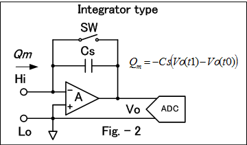
When using the capacitor, there is an integral type that uses the amplifier, and the shunt type that measures the voltage at both ends by simply pouring the electric charge measured by the capacitor. Fig.-2 and Fig.-3 show the respective block diagram.
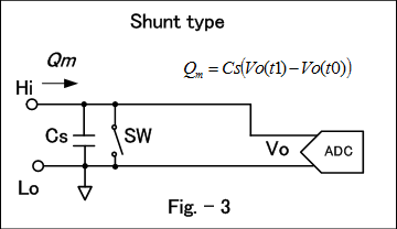
It is important that the input resistance of the amplifier used in the integral type and the voltmeter of the shunt type is high, and the current flowing to the input is small enough to prevent the loosing of the electric charge of the capacitor.
It is good as a principle, but in practice, there are limitations like the measurement and the threshold for the voltage applied to the capacitor that accumulates the electric charge, and hence it is impossible to keep charging the measured electric charge infinitely, and necessary to discharge. In general, the function (assume to call it as Reset) that makes the voltage to act on the capacitor by discharging to the predetermined state (usually 0 V) is provided, and the series of measurement is made after making the reset. In this case, we can make the measurement continuously until the measured quantity of electric charge reaches the decided value, but when it reaches, it is necessary to reset. Normally, it is not possible to measure during the reset operation, and hence a complete sequential measurement cannot be done without time limitation.
The quantity of electric charge can also be obtained by the time integration of the current as described in the previous paragraph. In this case, basically there is no restriction to the principle of current measurement. Many ammeters use the principle of passing the electric current at resistance and measuring. The quantity of electric charge can be measured by such a resistance sense type ammeter and time measurement. In such a case, there is no need to reset, and hence this is suitable when making continuous measurement over a long period of time, and when the time fluctuation of the quantity of electric charge is not high.
2. Integral type electric charge meter
This chapter explains the often-used integral type electric charge meter.
2.1 Principle of measurement
The block diagram Fig.-2 explains the principle of measurement of the integral type quantity of charge meter.
The switch SW is kept open during the measurement. The output voltage Vo of the amplifier does not change if there is no flowing in and out of the electric charge in the measurement state.
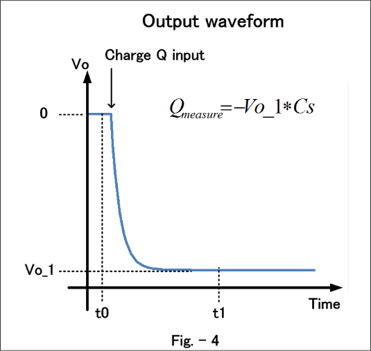
There is no electric charge in Cs when starting the simple measurement and Vo is assumed as 0. The voltage of V=Q/Cs acts at the capacitance when electric charge Q flows, and the electric charge is accumulated in the capacitance Cs. Therefore, the output voltage of the amplifier becomes Vo_1 = -Q/Cs. The quantity of electric charge is calculated from this output voltage as Qmeasure = -Vo_1*Cs. Fig – 4 shows the output waveform of the amplifier.
It is more commonly considered by the difference during the starting and ending of measurement. The amplifier output at t0 during the measurement start is assumed as Vo(t0), and the amplifier output at t1 during the measurement end is assumed as Vo(t1). The change of the potential difference acting at Cs is Vo(t1) - Vo(t0), and hence the quantity of electric charge Qm flowing during the measurement period can be obtained as Qm = -Cs(Vo(t1)-Vo(t0)).
When the Vo is within the operating range of amplifier or ADC, continuous measurement is possible. After the measurement start at t0, the Vo is measured at t1, t2, t3…, and the quantity of electric charge between each time can be obtained.
After completing the series of measurement, and before taking the next measurement, the accumulated electric charge in Cs is discharged by closing the switch SW, and returned to the initial state.
First, the low input voltage drop is the advantageous point of this method. Normally, the offset voltage level of the amplifier (generally, it is op-amp) used is less than few mV, and the fluctuation during the measurement is also extremely small.
The quantity of electric charge flowing can be accurately measured even if there is capacitance such as cables in the input portion, because the equivalent input impedance is low. It is also strong against the leakage due to voltage drop of the input portion.
The voltage acting at the accumulating capacitance Cs can be sufficiently increased, and hence it is easy to do the steady measurement at high resolution.
2.2 Factors of error margin and noise
This chapter explains the error margin of the electric charge measurement meter and noise factor.
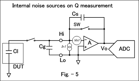
Fig.-5 shows the element of noise written in the block diagram when measuring the electric charge accumulated in capacitance CI as DUT.
Here
Cl: Capacitance of DUT
Cg: Capacitance between Hi and Lo
Normally, the capacitance of the connecting cable is the major part.
Cs: Capacitor for sense
Each element of error margin and noise is shown below.
a) Characteristics of Cs
The applied voltage dependency and the dielectric absorption characteristic of the capacitor influence the variation due to the error margin and the measurement time of the quantity of electric charge measurement, and hence it is important. The parts with adequately good characteristic are selected and used in the measuring device, to meet the specification.
b) In1: Current noise and bias current of input portion
The input bias current of the amplifier and the current noise are mostly the major part. The leakage current held by the switch SW for the electrical discharge and the leakage current of the connection cables etc. are also the current noises.
The bias current (Ib) is directly added up during the measurement time and becomes the error margin for Qe = Ib*(t1-t0). It is important that the bias current including the amplifier selection should be less, when measuring small quantity of electric charge. When the measurement time is long, then this error margin increases, and hence it becomes disadvantageous to spend a longer measurement time than the necessary time.
The current noise (AC) shows as the variation of the measurement result, and similarly the setting of appropriate measurement time is important because the long measurement time becomes disadvantageous.
c) Vn1: Input referred voltage noise of amplifier
The noise of Vn1*(Cs+Cg+Cl)/Cs shows in Vo due to this noise. When considering the effect of this noise, it is preferable that Cg and Cl are small. Cl is the measurement target and hence cannot be changed, but Cg is the connecting cable etc. and can be handled. When comparing the Cs and Cl, and if the Cg is small, it can be said that it is not the major part for this noise, and hence it becomes the rough standard when considering the size of Cg.
2.3 Application to other usages
In this chapter, let us consider the use of the electric charge meter in other measurements.
a) Ammeter
The current can be calculated if the quantity of electric charge and the time it was measured is known, and can be used as an ammeter as mentioned before.
When considering the resolution of the quantity of electric charge that can be measured, it is possible to measure up to small point as the current resolution. It is necessary to do the electrical discharge, and as a whole, it is intended for the measurement of less current.
Fig.-6 shows the block diagram of a general ammeter. The convergence system when current changes is decided by the time constant of Rs and Cs, and this time constant becomes long in the circuit for the small current measurement.
It is normal that the convergence of electric charge meter of Fig.-2, has become fast. It becomes advantageous if the change of current is to be seen in the measurement of the minute current region, and the measurement of current with big change.
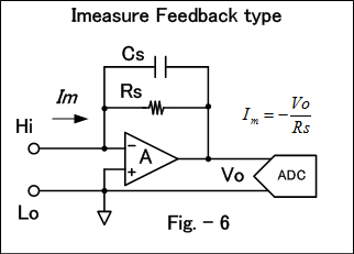
In the electric charge meter, the maximum quantity of electric charge and resolution that can be measured at a time is decided, and hence if the measurement time is changed, then the current range and the resolution that can be measured will change.
b) Capacitance measurement
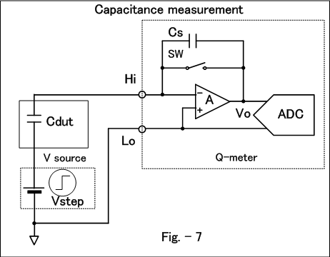
We can also perform capacitance measurement by combining with the voltage source that can apply the step voltage. Fig.-6 shows that connection. This is the case when the measurement target is not grounded.
The measurement before and after the application of step voltage Vstep is done, and the values are assumed as Qm1 and Qm2. The quantity of electric charge that flows due to the applied voltage becomes Qm2 - Qm1. It can be calculated as Cdut = (Qm2 - Qm1) / Vstep.
When seeing the formula to calculate the capacitance, it is clear that the accuracy and the noise of the voltage source that applies the step voltage directly affect the accuracy and the noise of the measurement result.
When the electric charge meter is floating, the capacitance of the capacitor grounded to one side can also be measured.
The continuous measurement of the leakage current and the capacitance of capacitor connected as shown in Fig.-7 can be done by using the method of current measurement and capacitance measurement described here.
2.4 Electric charge meter of B2985A/87A
This chapter gives a simple introduction of quantity of electric charge measurement function of B2985A/87A electrometer / high resistance meter.
Minimum range is 2 nC (Resolution 1 fC), and maximum range is 2 μC.
Integral type is used. It has the following functions and features.
When the quantity of electric charge reaches the specified level, it has the function (automatic electrical discharge function) to discharge (Reset) so that the quantity of electric charge does not reach the maximum range. As a result, it can be kept in the state to start the measurement at any time.
Generally, the input voltage drop in the integral type is very small, and the value is less than or equal to 20 uV. It can be adjusted during the self-calibration.
When considering the case of using it as the ammeter mentioned above, if the measurement time of 100 ms at 2 nC range is assumed, then the maximum current is 20 nA and the resolution is 10 fA. It has the ability to measure the equivalent minute current.
3. Measurement
This chapter describes the points we should consider during the measurement to get a smaller error margin and steady result.
3.1 Notes for measurement
The points to be noted when measuring the small quantity of electric charge are common when measuring the minute electric current. It is good to refer to the paragraph of “Connecting DUT” in the “Low-level current measurement using B2980A series” of the high sensitivity measurement knowledge portal.
a) External noise
The electrical noise that enters the measurement system from the outside often enters through the capacitive coupling.
The noise electric charge enters if there is a capacitive coupling between the items causing the power line and various voltage changes. It is always necessary to note that there is power supply wiring everywhere.
When the capacity between the electrified items changes, it still becomes noise. Humans are also usually electrified, and hence it affects when working at the place seen from the wiring for measurement.
As a response, it is important to reduce the capacitive coupling between the items that become the noise source, and shielding becomes the basic.
If the cycle is established like the power line, then the noise can be reduced by measuring at intervals of the multiple of cycle.
For the long noise of the cycle, it is effective to reduce the measurement time as much as possible.
b) Cable / mechanical noise
When vibration is inflicted on the cable, the friction of the conductor and the insulator causes electrification, and it becomes the noise electric charge. Some items cause the electric charge due to the piezo effect when pressure is applied, and it still causes the noise.
It can be reduced by taking care to avoid the vibration and excessive pressure. The normal cable can easily become a problem, and hence it is fixed so that it becomes difficult to inflict the vibration. However, very strong fixing and extreme bending should be avoided.
The coaxial and tri-axial cable with measures for reducing the current (electric charge) noise during vibration is called low noise cable. Concretely, a conductive layer is often provided at the insulator surface of the contact parts of the shield line and the insulator that can easily cause the friction electric charge. Using this kind of cable can reduce the cable noise greatly.
If the cable vibrates, then the vibration is transmitted to the parts connected to the cable like the connector, and becomes the source of the noise, and hence the vibration measures such as fixing is important even when the low noise cable is used.
c) Leakage current
The bias current is present even in the electric charge meter itself, and the leakage current of each part of the connection up to DUT and the current due to the electrochemical reaction is flowing, and the electric charge can be measured even if the electric charge from the DUT is not present.
Caution is necessary because the influence often becomes big due to the dirt, temperature and humidity in surroundings of the signal wire. It is effective to perform differential measurement method. The measurement conditions like the measurement time etc. are made the same; the measurement is done without DUT, and subtracted from the result of the actual measurement. This prerequisite of this method is the small change for the leakage current that becomes the error margin.
If the measurement time is increased, then naturally the quantity of electric charge measured by the leakage current becomes high. Therefore, long measurement time becomes disadvantageous when the error margin by the leakage current is considered. In case of measuring the minute current, if averaging (integration) is done over a period of time, then it becomes advantageous in the aspect of noise, and hence it is often recommended, but the measurement of quantity of electric charge differs. If long measurement time is taken, the error margin and noise increase basically, and hence care should be taken so that the measurement time is not too long for the necessary time such as the divergence time etc.
Conclusion
From the basic points for the measurement of quantity of electric charge to the points to be noted during actual measurement was described.
Mostly, the points related to the small quantity of electric charge are written, and there are a lot of common points for the points to be noted in case of minute current measurement.
Here, the measurement examples were not given, but the matters given here shall be applied in the actual measurement, and a steady measurement with very small error margin shall be obtained.