
Power Spectral Density (PSD) Test
散页
Power Spectral Density
Automotive Ethernet provides vehicles with faster data communications which is vital for today’s vehicles and the connected vehicles of the future. An essential component of validating an automotive Ethernet transmitter is the power spectral density (PSD) test, which measures a signal's power content versus frequency. It shows how the energy of a signal is distributed over the frequency spectrum. A PSD test is used to characterize broadband random or noise-like signals. The amplitude of the PSD expressed in dBm/Hz is normalized by the spectral resolution employed to digitize the signal.
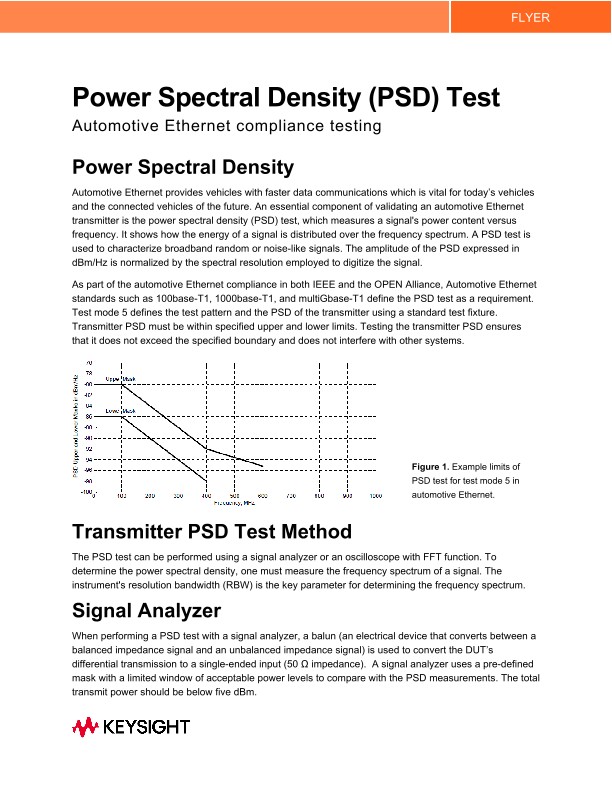
As part of the automotive Ethernet compliance in both IEEE and the OPEN Alliance, Automotive Ethernet standards such as 100base-T1, 1000base-T1, and multiGbase-T1 define the PSD test as a requirement. Test mode 5 defines the test pattern and the PSD of the transmitter using a standard test fixture. Transmitter PSD must be within specified upper and lower limits. Testing the transmitter PSD ensures that it does not exceed the specified boundary and does not interfere with other systems.
Transmitter PSD Test Method
The PSD test can be performed using a signal analyzer or an oscilloscope with FFT function. To determine the power spectral density, one must measure the frequency spectrum of a signal. The instrument's resolution bandwidth (RBW) is the key parameter for determining the frequency spectrum.
Signal Analyzer
When performing a PSD test with a signal analyzer, a balun (an electrical device that converts between a balanced impedance signal and an unbalanced impedance signal) is used to convert the DUT’s differential transmission to a single-ended input (50 Ω impedance). A signal analyzer uses a pre-defined mask with a limited window of acceptable power levels to compare with the PSD measurements. The total transmit power should be below five dBm.
Oscilloscope
When using an oscilloscope to measure PSD, the DUT’s differential transmission can be connected directly to the scope’s input channel (100 Ω impedance). The oscilloscope’s fast fouier transfer (FFT) math function calculates the power spectral density. Measurements are averaged over a 60-second acquisition to determine the signal’s frequency and mitigate random noise. A pass/fail mask, defining acceptable limits, is applied to the results. If all measurements are within acceptable limits, the test will pass. If there are outlying measurements, the test will fail.
Note: Because of the balun component in the measurement, the PSD measurement made with a spectrum analyzer interfaced with a balun and an oscilloscope makes a 3dB difference in power level. The scope’s reported signal power or PSD needs to be subtracted by 3 dB to match up with that of a spectrum analyzer. Keysight’s automotive ethernet transmitter compliance test automatically compensates the 3dB difference when the test configuration is correctly selected and gives the accurate PSD reading regardless of the type of instrument.
Summary
Power spectral density is a key measurement for automotive Ethernet and must comply with IEEE specifications. A signal analyzer or an oscilloscope can be used to ensure the signals are compliant, as described in this tip. An important thing to note is the expected 3 to 4 dB difference in measured results between the signal analyzer (with single-ended inputs and 50 Ω impedance) and the oscilloscope (with differential inputs and 100 Ω impedance). More information on can be found on resolving this measurement difference in Resolving PSD Measurement Differences flyer 5992-4153EN.