
Using X-Parameters PathWave RF Synthesis (Genesys) and PathWave System Design (SystemVue)
技术概述
PathWave RF Synthesis (Genesys) and PathWave System Design (SystemVue)
You’re convinced (as we are) that X-parameters provide the very best kind of nonlinear model for use in an RF System simulation, so two questions arise:
1. Where do they come from?
2. How do I use them?
There are only two ways to generate an X-parameter model. One is to measure a device yourself using a nonlinear vector network analyzer (NVNA). If you’re lucky enough to have such a measurement system, you’re all set. But there’s another way to get them: PathWave Advanced Design System (ADS) can turn a circuit schematic into an X-Parameter file that can be consumed in PathWave RF Synthesis (Genesys) or PathWave System Design (SystemVue). That process has been outlined in another Technical Overview.
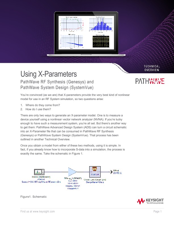
Once you obtain a model from either of these two methods, using it is simple. In fact, if you already know how to incorporate S-data into a simulation, the process is exactly the same.
Wait a second, there’s no X-Param part on that schematic… so what gives? The model is hidden inside the Circuit_Link, which is always a good idea. Inside a Circuit_Link network, you can place multiple nonlinear devices with additional passive components in a single nonlinear analysis. As the parts interact according to their frequencies, load pull impedances, DC bias, signal power, etc., the overall result is presented to the RF System simulator with greater accuracy than system-level behavioral models would have provided by themselves into static loads.
Pushing into the Circuit_Link, we see the X-Parameter model in Figure 2. The IPROBE is there in case we want to calculate power added efficiency or a similar measurement.
The XPARAMS part points to an amplifier’s X-parameter file. This device has nominal Gain = 20 dB and TOI = +25 dBm. An XPARAMS part functions just like an SPARAMS part does for Sdata.
X-Parameters support multi-port devices, mixers, and any other nonlinear RF device.