
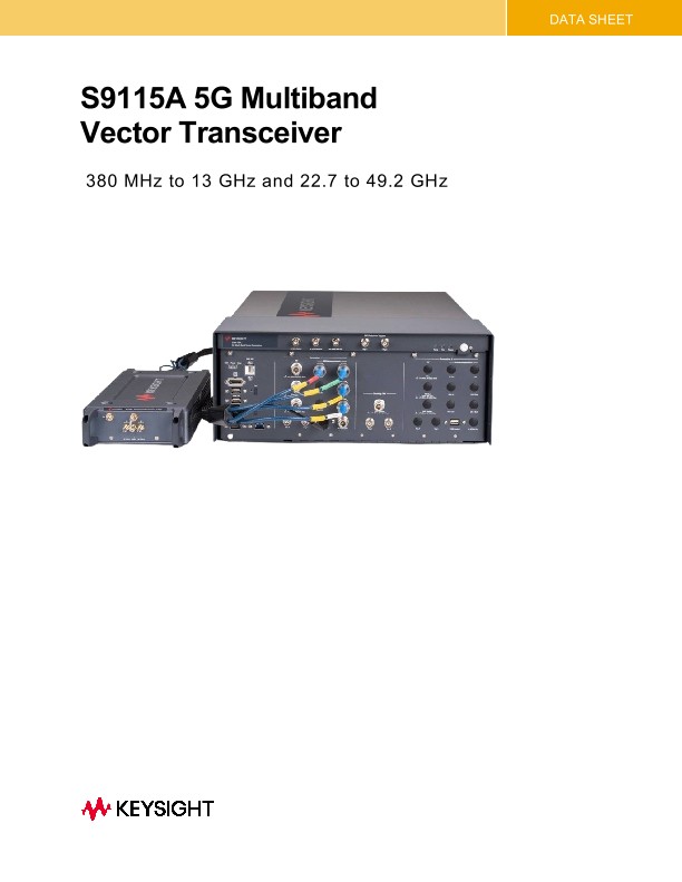
S9115A 5G Multi-Band Vector Transceiver
技术资料
System Performance
Conditions
Information and data contained in this data sheet is subject to change without notice.
In addition to the following conditions, the S9115A system performance, documented in this data sheet, is valid for an ambient temperature of 25 °C unless otherwise noted.
• The system is within its calibration cycle.
• The system has been stored at an ambient temperature within the allowed operating range for at least two hours before being powered on.
• The system has been powered on continuously for at least 60 minutes warm-up time, with the IQ Analyzer or X-Series application (e.g. 5G NR) running, and the M1749B mmWave Transceiver powered on (verify that LEDs are on). If the system met these warm-up requirements and there is a brief power shutdown, such as a system reboot, allow 20 minutes of warm-up time after the system is powered back on.
• The alignments have been run in order of “Align Now All”, “Align RRH LO Power”, “Align IF Cable” and “Align RRH Amplitude” for the first use, after the warm-up period.
• The “Align Now All” alignments have been run within the previous 7 days, after the warm-up period.
• A “Fast Alignment” has been run:
o within the previous 8 hours
o If the temperature has changed more than 5 °C from when the previous “Fast Alignment” was performed
• The alignments have been run in order of “Align Now All”, “Align RRH Amplitude”, after the warm-up period:
o If more than 30 days have elapsed since the previous “Align RRH Amplitude” alignment.
• If the IF cables have been disconnected, reconnected, or replaced it is recommended to run “Align Now All”, “Align RRH LO power “, Align IF Cable” and “Align RRH Amplitude”.
Characteristics
• The characteristics provided in this data sheet for operation at or below 13 GHz are a subset of the specifications for the Keysight M9415A PXIe VXT Vector Transceiver module. For the most recent detailed performance information, refer to the M9415A Data Sheet (literature no. 3120-1518EN). Note that the performance characteristics in that data sheet apply at the input/output connectors of the M9415A module, but in the S9115A system, there is approximately 0.25 to 0.5 dB of insertion loss between the S9115A front panel connectors and the M9415A due to the M9155C switch module and cabling.
• The Sub 13 GHz amplitude characteristics in this data sheet include the effects of the added system insertion loss.
• The M9415A-001 in this S9115A 5G Multi-Band Vector Transceiver is configured with: Option F12(Frequency Range, 380 MHz to 13 GHz), Option B12 (1.2 GHz BW), Option M05 (512 MSa memory), Option 1EA (High Output Power).
S9115A Standard Configurations
This data sheet contains system performance for the S9115A base system that is available in three standard configurations with multiple input and output connectors. Each configuration is specified with the F49 option which extends the full frequency range to 22.7 GHz to 49.2 GHz. If the F43 option is purchased, then the upper frequency is limited to 43.5 GHz:
• Keysight S9115A-TR1 5G Multi-Band Vector Transceiver
• Keysight S9115A-TR2 5G Multi-Band Vector Transceiver
• Option F43 - mmwave Transceiver Range 22.7-43.5 GHz
• Option F49 - mmwave Transceiver Range 22.7-49.2 GHz
S9115A connectors (Ports 1 to 6)
Note: Please refer to figures 1 and 2 below for locations of the referenced connections.
Each S9115A standard configuration has a different set of output and input connectors (ports):
• All S9115A-TR1 configurations have mmWave ports on the M1749B mmWave Transceiver that are RF Tx/Rx 1 and RF Tx/Rx 2
• All S9115A-TR1 standard configurations have RF Transceiver RF ports RF Out and RF In
• All S9115A-TR2 standard configurations have two sets of mmWave ports and two sets RF ports:
o M1749B mmWave Transceiver 1 has ports RF Tx/Rx 1 and RF Tx/Rx 2
o RF Transceiver 1 has ports RF Out and RF In
o M1749B mmWave Transceiver 2 has ports RF Tx/Rx 1 and RF Tx/Rx 2
o RF Transceiver 2 has ports RF Out and RF In