
Digital Video Broadcasting (DVB) Satellite Communication Analysis
技术概述
DVB-S2 / S2X SatComm Modulation Analysis
The 89600 VSA software’s DVB SatComm (Satellite Communication) measurement extension, 89601DVBC, provides a comprehensive array of analysis capabilities in frequency, time, and modulation domains for DVB-S2 and DVB-S2X signals based on ETSI EN 300 307 specification (www.etsi.org). DVB-S2 / S2X is one of over 75 signal standards and modulation types supported by the 89600 VSA software, a comprehensive set of tools for demodulation and vector signal analysis. These tools enable you to explore virtually every facet of a signal and optimize even the most advanced designs. As you assess and focus on your design tradeoffs, the 89600 VSA helps you cut through the complexity.
The software delivers simultaneous frequency, time, and modulation-domain analysis results within a single measurement. By configuring result traces for spectrum, acquisition time, and DVB-S2 / S2X specific modulation quality traces and tables, engineers can easily identify signal characteristics and troubleshoot issues such as intermittent errors or recurring synchronization failures.
To streamline automated testing, .NET API and SCPI remote interfaces are available to accelerate design processes, enabling a smoother transition to design verification and manufacturing phases.
Analysis and Troubleshooting
Perform DVB-S2 / S2X transmitter measurements
89601DVBC supports DVB-S2 / S2X modulation analysis measurements according to ETSI EN 302 307-1 (DVB-S2) and 302 307-2 (DVB-S2X) specifications. Supported features include:
• Comprehensive PLFrame signal analysis for each frame part: SOF, PLSCODE, Pilot, and Data
• Compatibility with all standard-defined MODCOD formats, encompassing a combination of code rate and modulation from QPSK, Pi / 2-BPSK, 8PQSK, 16 / 32 / 64 / 128 / 256 APSK
• Options for standard-defined roll-off factors from 0.05 to 0.35 or customized roll-off factors
Effortless Setup with Comprehensive Parameter Control
Configure your VSA effortlessly using the intuitive graphical user interface (GUI). This measurement provides a fully DVB-S2 / S2X standard-based representation of the VSA measurement setup, with each Demod Properties menu item corresponding to a set of related parameters.
The Dynamic Help feature allows for easy access to help text, enabling an understanding of the DVB-S2 / S2X format and the features available for option 89601DVBC. Detaching and repositioning the Dynamic Help window, as shown in Figure 2, enables easier viewing as it adjusts to your menu choices. You can also lock it to stay fixed on important Help data topics.
Testing Beyond EVM with BER
In addition to the conventional demodulation analysis results like EVM, the DVB-S2 / S2 measurement extension also provides Bit Error Rate (BER) results. This allows users to verify the accuracy of the transmitted signal’s CRC and payload decoding. However, we must consider where in the functional block diagram we are wishing to compare measured versus expected bits. The following figure shows the functional block diagram of a DVB-S2 system (taken from the ETSI standard).
Understanding DVB-S2 / S2X signal quality
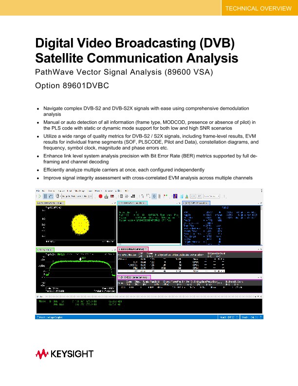
Thanks to the VSA’s great documentation, signal analysis configuration and trace types, you may learn about the structure and quality of the transmitted DVB-S2 / S2X signal. You have full autonomy and complete flexibility to choose the trace format and the number of concurrent traces. Figure 6 shows a downlink DVB-S2X signal example. The different traces provide a comprehensive view of the signal, and many more views are possible.
Description of some of the digital demodulation traces
• Trace A (top left, labeled “Meas Time”) shows a composite IQ constellation of the demodulated signal containing 16APSK
• Trace B (bottom left, labeled as “Spectrum”) displays the spectrum of 3 component carriers, each with 400 MHz bandwidth
• Trace E (top center, labeled as “Decoded Info”) presents the decoded results for each frame, including Frame Index, PLSCODE, Mod Format, Type, Pilot On / Off, Payload LDPC Parity, Payload Header and CRC Pass / Fail
• Trace C (top right, labeled as “Syms / Err”) shows the demodulation results for the specified carrier, featuring EVM, Mag Err, Phase Err, Freq Err, Channel Power, IQ Offset, IQ Gain, IQ Skew, and BER results
• Trace D (bottom center, labeled “ Summary”) shows the whole frame result for each segment (including SOF, PLSCODE, Pilot and Data) and results with EVM, Power, First Symbol, Num of Symbols, Modulation Format, and BER results
• Trace F (bottom right, labeled “Carrier Summary”) presents the results for all configured carriers, including Carrier#, Center, Offset, Symbol Rate, EVM, Channel Power, Freq Err, Sym Clock Error, Mag Error, Phase Error, and BER results
Cross-Correlated EVM
Cross-Correlated EVM (ccEVM) is a technique used to extend the dynamic range of a receiver for optimal EVM performance. This method involves two receivers capturing and demodulation the same signal simultaneously. The software performs a cross-correlation calculation on the error vectors to cancel out any uncorrelated noise added by the receivers, resulting in an EVM measurement of significantly higher fidelity. Consequently, the resulting ccEVM measurement primarily consists of the noise and distortion effects from the device under test (DUT). In the case of an amplifier measurement, the ccEVM would represent the noise at the input of the amplifier plus the DUT noise and distortion effects. Note that this feature within 89601DVBC requires the 89601EVMC (EVM measurement fidelity) option.