
Accurate Simulation Models Yield High-Efficiency Power Amplifier Design
Article Reprints
The design of RF and microwave power amplifiers continues to be somewhat of an art yet to be reduced to a systematic repeatable design practice on a wide-scale basis, despite the many excellent treatments of the subject in the literature (e.g., [1]) and a number of courses. The general unavailability of sufficiently accurate and reliable nonlinear models for power transistors has been a major factor in limiting the accuracy of power amplifier (PA) simulation results. Suitable nonlinear models must properly treat the nonlinear and combined dc/ac analysis required for proper power compression and efficiency simulation under varied load and bias conditions. In this article, an accurate nonlinear transistor model is shown to form the basis for a systematic simulation-based design procedure for a microwave PA. As an illustration of the procedure, a high-efficiency PA was developed with excellent first-pass performance results. This circuit was designed using a nonlinear transistor model and passive component models commercially available from University of South Florida (USF) spin-out company Modelithics, Inc. [2], [3] in combination with Agilent Technologies Advanced Design System software [4]. An 8-W PA with 62% efficiency was achieved at 1.3 GHz, without modification of the circuit. This circuit was awarded first place in an IEEE sponsored PA design competition. (See “Student High Efficiency PA Design Competition.”)
Design Goals and a Simulation- Based Process for PA Design
The initial design goals for the PA are shown in Table 1. These goals are thought to be reasonable based on previously reported achievements in highefficiency PA design. One push-pull amplifier design detailed in the literature has shown 60.9% power-added efficiency (PAE) at 4.15 GHz with an output power of 28.2 dBm [5], and another push-pull design has been reported to provide 63.8% PAE at 3.55 GHz and 28 dBm output power using harmonic tuning [6]. Such results show that achieving over 50% PAE for the targeted singleended Class AB design should be a reasonable goal. For the design described in this article, a center frequency of 1,489 MHz was targeted along with a 1-dB compression power (P1dB) goal of 38 dBm output at 25 dBm input power (Pin). The goal was to achieve maximum PAE once the other minimum requirements had been met, and a PAE of over 50% was targeted for Class AB operation. A Fujitsu FLL120MK GaAs FET was selected to achieve these goals. According to its data sheet, this device is capable of 10 W at 2.3 GHz with greater than 40% efficiency [7]. Table 2 shows the systematic design process followed for the developed amplifier. The key to the success of the process was to have suitable models available for all the active and passive components and transmission line structures used. The transistor model provided by Modelithics for the FLL120MK was an EEHEMT model [4], developed using IV and multiple-bias S-parameter measurements, with the aid of Agilent’s IC-CAP extraction software. The model was independently validated at high power with a Maury Microwave ATS load/source pull system. The passive surface-mount device (SMD) models for the utilized Coilcraft Air Coil inductors, Toko 0805 Inductors, and ATC 0805 capacitors were supplied by Modelithics. The models were developed from S-parameters measured on multiple substrates in combination with accurate effective series resistance (ESR) measurements [2]. These models have as input parameters the nominal component value and substrate properties (including thickness and dielectric constant), allowing for optimization of component values in Step 8, while fully addressing parasitic effects. These models were added in Step 6, along with microstrip (MS) transmission line models built-in to ADS, after the initial design was completed using Steps 1–5.
Load Pull and Source Pull Simulation
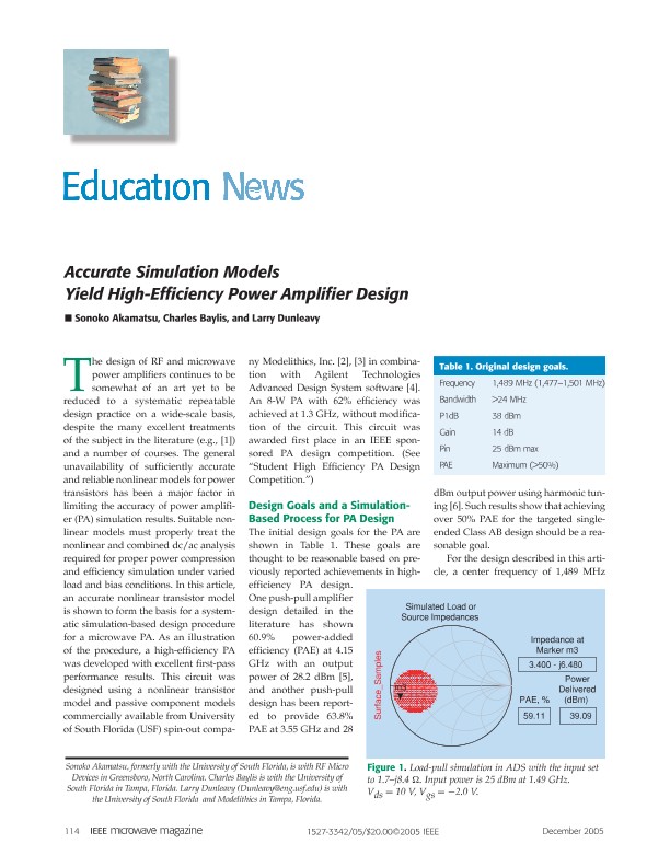
Load pull simulations, enabled by the nonlinear transistor model, were used in ADS to select optimum conditions for high efficiency. The optimal load impedance was determined by initially setting the input impedance to a conjugate gain match. This was done using a 50-_ simulation using the aforementioned nonlinear model for the Fujitsu FLL120MK [3]. The load- and source- pull simulation results are summarized in Tables 3 and 4, respectively. In addition, Figures 1 and 2 show the simulated load- and source-pull results, respectively, for the impedance values providing maximum PAE. Asource-pull simulation was then performed, focusing on high-efficiency tuning. Based on iteration of results from load- and sourcepull simulation at several different bias conditions, a bias condition Vds = 10 V, Vgs = −2.0 V, and an optimum load impedance were selected. These initial simulations indicated that 59.8% PAE was possible with a source impedance of 2.19–j6.25 _ and a load impedance of 3.40–j6.48 _. A separate harmonic balance (HB) power simulation was performed under the same source/load impedances to confirm the simulation result of PAE = 59.8% and Pout = 39.3 dBm at an input power of 25 dBm.
Matched Amplifier
The ADS DesignGuide tool, “Lumped Multi-Element Z-Y Matching Networks,” was used to determine lumped element output and input matching networks (MNs) [4] that transformed 50 _ into the desired optimum load and source impedance values. Figures 3–5 show the ideal MNs and results. Both small- and large-signal simulations were next performed with ideal passive components used to realize the required matching. A 10-V drain-source voltage and a −2.0-V gate-source voltage were used for the initial transistor bias. Figure 6 shows the small-signal simulations. The result shows 16.2-dB gain at 1.49 GHz, which satisfies the design goal in Table 1. Large-signal simulation was performed using a template under the “DesignGuide” from the ADS schematic window. Figure 7 shows the ideal largesignal simulation schematic. The result in Figure 8 shows 62.2% PAE, output power of 39.38 dBm, and input power of 25 dBm. These results are slightly better than those achieved under the initial load/source pull simulation. The substrate-scalable and part-valuescalable SMD models were next combined with transmission-line models using built-in ADS elements, MS line (MLIN), MS step (MSTEP), and MS TEE (MTEE). The 50-_ width for MS line was calculated by the ADS transmission line calculator, LineCalc, to be 2.86 mm. These calculations were based on 59 mil thick FR4 substrate information (Er = 4.3).